


Why Foot Health and Spa Care Are Important for Overall Wellness
 Many people pay attention to skincare, fitness, and nutrition, but often forget about foot health. The feet carry the body every day and absorb constant pressure from walking, standing, exercising, and daily activities. When foot problems develop, they can affect comfort, movement, posture, and overall quality of life.
Foot health is more important than many people realize. Pain, swelling, poor circulation, and skin issues in the feet can impact the entire body. Some foot conditions may even be connected to larger health concerns such as diabetes, poor circulation, joint problems, or nerve issues. Because of this, proper foot care should be part of a person’s overall wellness routine.
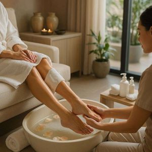
Spa treatments focused on foot care are also becoming more popular. MyEthosSpa now offer treatments that support relaxation while helping improve foot comfort and appearance. These services can include foot massages, exfoliation, hydration treatments, circulation therapies, and specialized foot wellness programs.
Modern wellness trends now focus on preventive care rather than waiting for discomfort to become severe. People are becoming more aware that healthy feet support mobility, posture, balance, and long-term wellness. This growing awareness has increased interest in foot-focused wellness and spa services.
The connection between health and spa care creates a more complete approach to self-care. Foot wellness treatments not only help people relax, but may also support circulation, reduce tension, and improve overall comfort. When combined with proper medical care and healthy habits, these treatments can help maintain better foot health over time.
Common Foot Health Problems and Their Impact on Daily Life
Foot problems can affect people of all ages. Some issues develop because of lifestyle habits, while others may be linked to medical conditions, aging, or improper footwear. Even small foot problems can eventually affect walking, balance, and overall mobility.
One of the most common issues is foot pain caused by standing or walking for long periods. People who work in healthcare, retail, hospitality, or construction often place heavy pressure on their feet every day. Without proper support, this can lead to soreness, swelling, and discomfort.
Poor footwear is another major cause of foot problems. Shoes that are too tight, lack support, or place pressure on certain areas of the feet may contribute to blisters, bunions, calluses, and posture problems. High heels can also place extra stress on the feet and joints.
Dry skin and cracked heels are also common concerns. The skin on the feet often becomes dry because of pressure, friction, and environmental exposure. If left untreated, cracked skin may become painful and increase the risk of infection.
Circulation issues can also affect foot health. Poor blood flow may cause swelling, numbness, or discomfort in the feet. People with diabetes are especially encouraged to monitor their feet closely because minor injuries may heal more slowly and become serious if ignored.
Athletes and physically active individuals may also experience foot strain and injuries. Running, sports activities, and high-impact exercise can place repeated stress on the feet and ankles. Proper recovery and foot care are important to help reduce strain and discomfort.
Foot problems can also affect posture and movement. When the feet are uncomfortable, people may unconsciously change the way they walk or stand. Over time, this may lead to discomfort in the knees, hips, and lower back.
Stress can even affect the feet. Muscle tension and poor circulation may increase discomfort and fatigue. This is one reason why relaxation-based foot treatments have become popular in wellness and spa settings.
Early care is important because small foot problems can become more difficult to manage if ignored. Regular foot care, supportive footwear, healthy habits, and wellness-focused treatments can help reduce many common issues before they become severe.
How Spa Treatments Support Foot Wellness and Relaxation
Spa treatments for foot wellness are no longer viewed as simple luxury services. Many people now use these treatments as part of their regular self-care and wellness routines. Foot-focused spa therapies can help improve comfort, support relaxation, and maintain healthier skin and circulation.
Foot massages are among the most common wellness treatments. Massage may help reduce tension, improve circulation, and relax tired muscles after long periods of standing or walking. Many people also find foot massages calming because the feet contain many nerve endings connected to different areas of the body.
Exfoliation treatments are also important for maintaining healthy feet. Dead skin buildup can make the feet rough, dry, and uncomfortable. Gentle exfoliation may help soften the skin and improve overall foot appearance.
Hydration therapies are commonly used to address dry skin and cracked heels. Moisturizing treatments help restore softness and reduce discomfort caused by dryness. This can be especially beneficial for people who spend a lot of time outdoors or wear open footwear regularly.
Some wellness centers also offer circulation-focused therapies. Warm soaks, hydrotherapy, and massage treatments may help improve blood flow and reduce swelling in the feet. Better circulation can support overall foot comfort and recovery.
Aromatherapy is another common addition to foot spa treatments. Essential oils and calming scents are often used to create a relaxing environment that supports stress reduction and emotional wellness.
Reflexology has also gained popularity in wellness settings. This therapy involves applying pressure to certain areas of the feet that are believed to connect to different parts of the body. While experiences vary from person to person, many people use reflexology for relaxation and stress relief.
Foot spa treatments may also encourage people to pay more attention to their foot health. Regular wellness appointments can help individuals notice skin changes, discomfort, or other issues early.
Wellness-focused foot care can be beneficial for older adults as well. As people age, foot comfort becomes increasingly important for maintaining balance and mobility. Gentle spa treatments may help improve comfort and relaxation for seniors.
Although spa treatments may support foot wellness, they should not replace medical care when serious conditions are present. Persistent pain, infections, severe swelling, or wounds should always be evaluated by qualified healthcare professionals.

 Diabetes is a condition that can harm both oral health and foot health at the same time. Scientists have long known that gum disease and other oral infections can worsen blood sugar control. Poor circulation and nerve damage in the feet are two of the most serious complications of diabetes. When these two systems — the mouth and the feet — are affected together, the risks multiply.
 There is no legislative provision requiring Health Canada to evaluate for approval the manufacture and sale of steroids and various ancillary products like sexual
  Life science research on foot problems show that factors such as age, obesity, mental health and vascular disorders can increase the risks of loss of balance that cause falls especially in women and older people.


 Stress is an unavoidable part of life, but chronic stress can wreak havoc on the body and mind. Prolonged
  Routine podiatric check-ups are among the preventive care treatments that health insurance usually pays for. Frequent podiatrist appointments help prevent difficulties and identify possible issues early on. Those with chronic diseases like diabetes, which can compromise foot health, especially need preventive treatment.
 Nootropic agents mainly improve blood flow. As more blood flows to the brain, it may be also beneficial for the feet as it reduces the chances of developing foot problems such as peripheral neuropathy.


